
- About Standard Sensors
-
Sensors
- Air Charge / Manifold Temperature Sensors
- Accelerator Pedal Sensors
- Anti-lock Brake (ABS) Sensors
- Brake Pad Wear Sensors
- Camshaft Sensors
- Crankshaft Sensors
- Coolant Temperature Sensors
- Exhaust Gas Temperature Sensor
- Knock Sensors
- MAP Sensors
- Mass Air Flow (MAF) Sensors
- Steering Angle Sensors
- Transmission Input/Output Sensors
- Vehicle Speed Sensors
- Yaw Rate Sensors
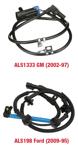
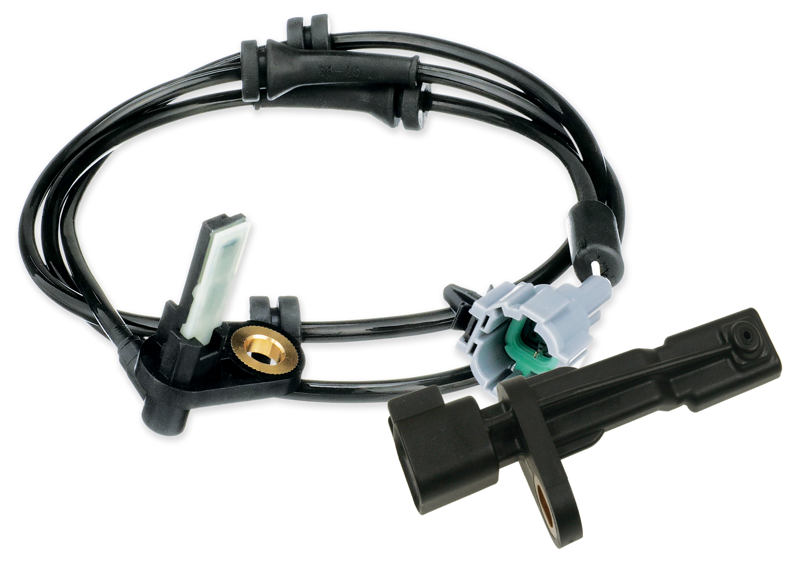
Anti-lock Brake (ABS) Sensors
ABS Sensors - Fast Facts
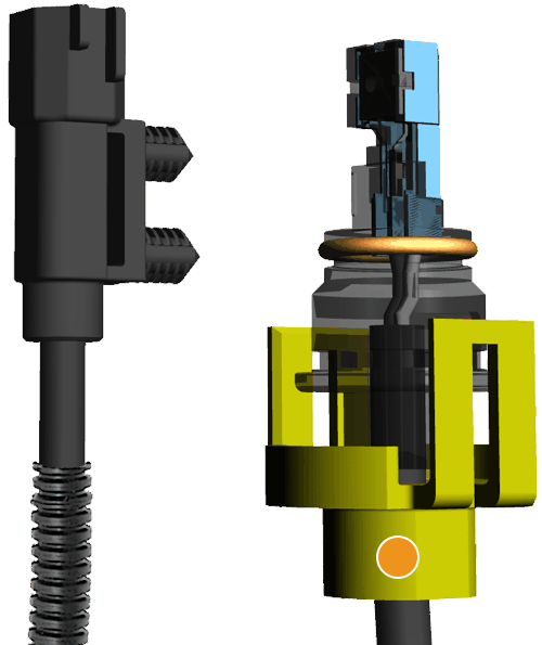
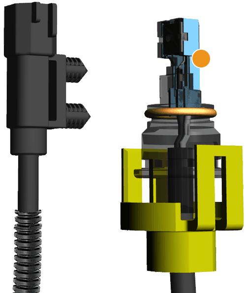
- The ABS sensor is typically located in each wheel hub/rotor on a four channel ABS system. Some rear wheel drive applications have the sensor mounted in the rear differential
- Generally these sensors will fail as a result of clogging from metallic debris, brake dust or dirt due to exposure to the harsh elements
- A failing sensor can illuminate the MIL or ABS warning lamp, and may cause failure of the anti-lock braking system to operate safely and properly
- An ABS sensor can be visually inspected and the wire winding and sensor harness can be tested for opens, shorts and proper factory specified resistance with an ohm meter
ABS Sensor Testing
Rigorous Testing Means a More Reliable Sensor
Extensive laboratory and real-life testing includes evaluating the following:
- Shaft speed vs. delta voltage
- Output voltage and variation to OE
- Magnetic field strength and air gap
- Output wave form and pulse width
ABS Sensors Testing – See how the rest of the pack stacks up
We left no stone unturned; performing extensive laboratory and real life testing that included measuring and comparing shaft speed vs. delta voltage, output voltage and variation to OE, magnetic field strength, air gap, output wave form, pulse width as well as a complete physical product comparison to OE.
The Findings
Competition ABS Sensors
- No Consistency in signal output performance.
- Inferior materials in the magnetic circuit which results in low voltage output and can lead to ABS system failure.
- No Consistency in critical sensor dimensions which establish the gap between the sensor tip and target wheel which can lead to the sensor tip hitting the spinning target wheel causing sensor damage.
- Inadequate quality inspection and product testing.
- No Consistency in matching OE for form, fit and critical function.
How Does the Competition Measure Up?
The competition didn’t physically match up. It measured 29-51% lower voltage output when compared to the GM sample, leading to potential system failure. In the Ford test, the competition measured 45-74% lower voltage, with resistance and inductance flaws that result in poor performance.
Standard® ABS sensors delivered a more consistent signal output performance, matching OE for output voltage, resistance and all critical measurables.