
Ignition Coil Operation
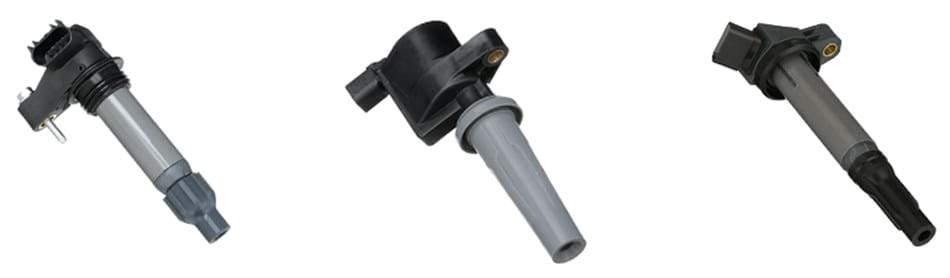
Coil-On-Plug Assembly
Coil-on-plug assemblies are designed to convert a low voltage (primary side) to a high voltage (secondary side) to fire the spark plugs. They perform the functions of both the ignition coil, which creates the spark energy, and the spark plug wire set, which delivers the high-voltage energy to the spark plug.
Today's coil-on-plug assemblies come in a variety of physical and wiring configurations. The typical configurations are two wires, three wires and four wires. Some ignition coils contain a solid state driver module, which is part of the ignition coil and is controlled by the Powertrain Control Module (PCM). Others have the primary winding wired to and directly controlled by the Powertrain Control Module. One of the circuits that should be common to all ignition coils is the battery voltage power supply.
Note: It is always recommended to refer to service information for the specific vehicle you are working on.
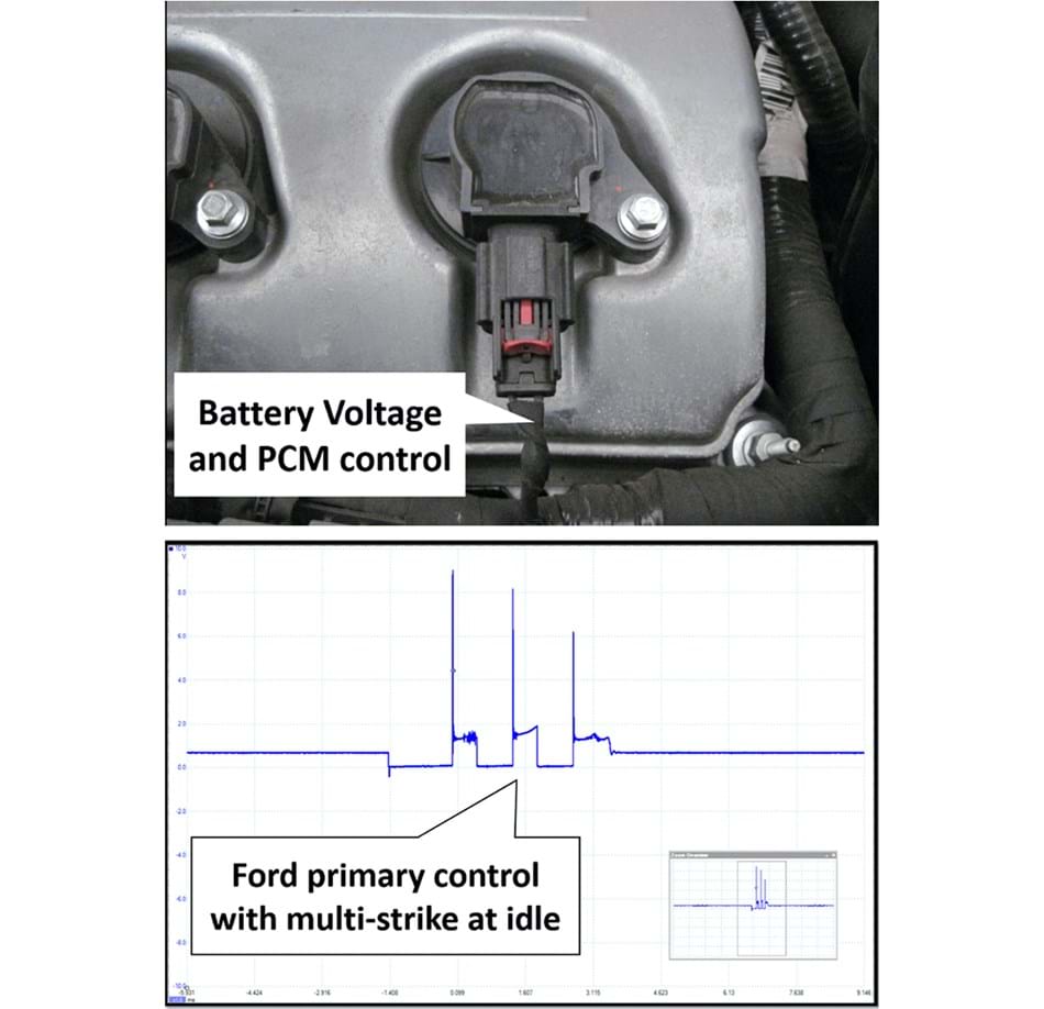
Typical Two-Wire Coil-On-Plug Assembly
The typical wiring configuration for a two-wire coil-on-plug assembly includes battery power supply and the direct control circuit (trigger) of the primary winding. This is very similar to the single ignition coil systems of the past. Most vehicles use single strike to control the primary. The Ford example below uses multi-strike at idle, meaning that it fires multiple times in one firing event.
Power Tip – Repeat Ford ignition coil failure. One or more coils may melt down and damage the computer’s ignition coil drivers. It is common practice to replace the ignition coils and spark plugs first then come to the conclusion that the PCM is faulty. During the PCM-replacement process, the old module’s information is removed in a process called inhaling. In order to do this, the original module is still connected to the vehicle and the key is turned on. If the ignition coil drivers in the original computer are damaged and with the wiring connected, the new coils installed are being heated to melting point. This ruins the new coils. Now when the new PCM is installed, it ruins the new PCM. The PCM should be installed with the power removed from the ignition coils or in a process called “As Built” data installation, which does not require the original PCM to be plugged in.
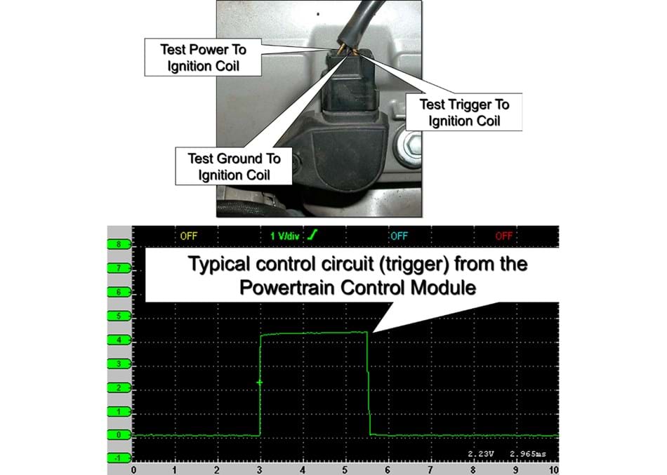
Typical Three-Wire Coil-On-Plug Assembly
The typical wiring for a three-wire ignition coil-on-plug assembly are battery voltage power supply, ground and control circuit (trigger) from the PCM to a transistor circuit in the coil on plug assembly.
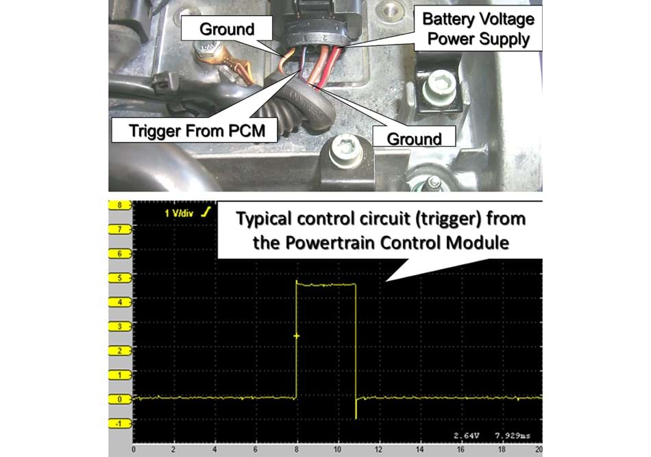
Four-wire coil-on-plug assemblies can involve a lot of commonality also, such as the battery voltage power supply, two ground circuits and the control circuit (trigger) from the PCM to the solid state driver module. Some applications may use one of the four wires of the coil-on-plug assembly as a feedback circuit to verify proper ignition coil system integrity.
Note: It is always recommended to refer to service information for the specific vehicle you are working on.
Typical Four-Wire Coil-On-Plug Assembly
Power Tip – Initial or repeat failure of ignition coil assembly's can be caused by inadequate or missing chassis/body grounds. A thorough inspection and verification of the chassis/body grounds needs to be performed to avoid repeat failures. Also, do not forget the condition of the spark plugs themselves as a contributing factor. When replacing an ignition coil that has failed, replacing the spark plugs and the other ignition coils is always recommended to prevent comebacks.